 ドキュメント
実験4 全自動ライントレース&色認識ボール打ちロボットプロジェクト
実験の目的:
-
PWM の基本的な動作原理を理解し、PWM による三輪二駆動台車の走行制御とサーボの首振り制御を実現します。
-
ライントレースセンサーの基本的な動作原理を応用し、ライントレースセンサーのデータ取得方法を習得します。
-
USART シリアル通信の仕組みを理解し、色認識センサーのデータを取得します。
-
三輪二駆動台車をベースに、ライントレースと色検出を組み合わせた総合制御プログラムを作成します。
-
STM32CubeMX で新規プロジェクトを作成し、MDK_ARM プロジェクトファイルを生成できるようになります。
-
keil IDE でユーザーコードを追加し、プロジェクトのテストができるようになります。
PWM の基本原理:
パルス幅変調(PWM)は、信号のデューティ比を調整することでモーターの回転速度とトルクを制御する技術です。
- PWM 信号の定義
デューティ比(Duty Cycle):PWM 信号の周期に対するハイレベル時間の割合です。デューティ比が高いほど、モーターにかかる平均電圧と電力が大きくなります。
周波数:PWM 信号の繰り返し周波数で、通常は数百 Hz から数 kHz の範囲です。
- PWM による DC モーター制御の動作原理
スイッチング制御:PWM 信号はスイッチング素子(MOSFET や IGBT など)を介してモーターへの電力供給を制御します。スイッチング素子は PWM 信号のハイ/ローに応じて高速にオン・オフを切り替え、モーターを制御します。
平均電圧:モーターが受けるのは PWM 信号の瞬時電圧ではなく平均電圧です。デューティ比を変えることで、モーターの回転速度を調整できます。
ライントレースの基本原理:
センサーの種類:
赤外線トラッキングセンサー:最も一般的に使われるタイプで、赤外線発光部と受光部で構成されます。
信号の送受信:
赤外線発光部:赤外線を照射します。光が床面に当たると、その一部が床面で反射されます。
受光部:反射光を受け取り、受光強度から床面の色や反射率を判定します。
検出:
主に白と黒のコントラストの検出に用いられます。黒い面は光を多く吸収し、白い面は光を多く反射します。
センサーが黒を検出すると、受光部の出力信号が変化します。
差動駆動の原理:
| 左右の車輪が同じ速度・同じ回転方向で前進します。 | 左車輪の速度が右車輪より大きいと、ロボットは右に曲がります。 | 右車輪の速度が左車輪より大きいと、ロボットは左に曲がります。 |
応用シーン
ライントレースロボット競技向けインテリジェント制御システム:ライントレース走行、色認識による照合、ロボットアームによるボール打ちのタスクを自動で完了でき、教育用ロボット競技や自動化された競技シーンに適しています。
機能要件:
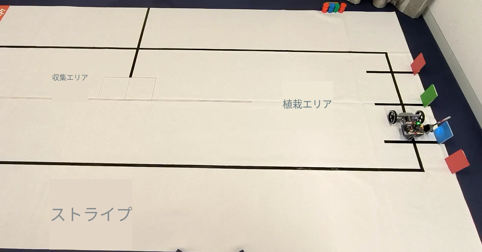
ロボットがライントレースで走行し、色を認識し、最後にロボットアームでボールを打ちます。ロボットはラインに沿って走行し、交差点(4 つのライントレースセンサーがすべて反応した状態)に来ると停止して色を認識します。次の交差点でも引き続き色を認識し、最後にロボットアームで打撃動作を模擬します。
ハードウェアの準備:
STM32 メインボード V1.3 * 1、ST-Link ダウンロードケーブル * 1、3S バッテリーボックス * 1、リチウム電池 * 3、ライントレースセンサー * 1、色認識モジュール * 1、サーボ * 1、USB データケーブル * 1
試作機の構成:
実験1 T 型フレームおよび三輪二駆動台車の構造設計
回路の接続:
ハードウェアモジュール
ヒント:ハードウェアおよびソフトウェア環境の設定
UNI-STM32 開発ボード【V1.3】の紹介
UNI-STM32 開発環境の設定【V2.0】
バッテリーおよび電源モジュールの使用上の注意(必読)
電子モジュールの紹介
ピンの説明
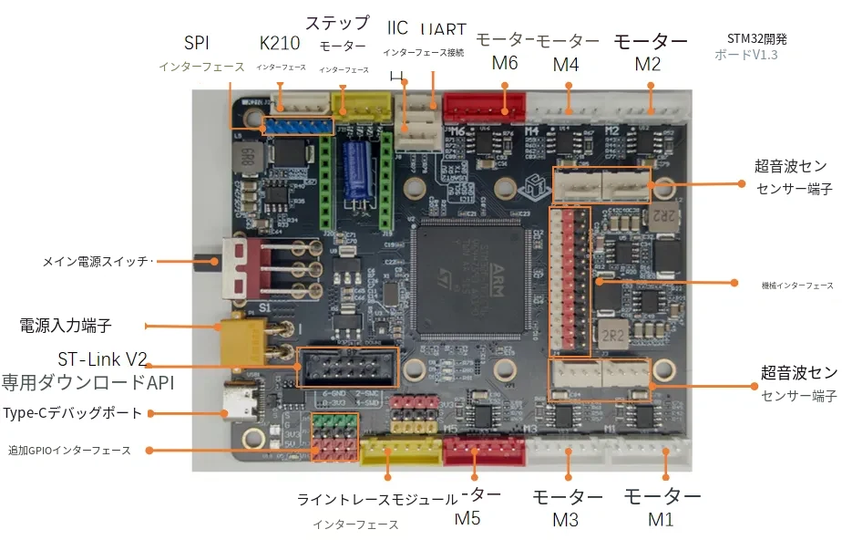
| 台車の電子部品 | STM32 メインボードのインターフェース/ピン | 4 チャンネルライントレースモジュール | STM32 メインボード ピン | 色認識 センサー | STM32 メインボード ピン |
|---|---|---|---|---|---|
| エンコーダ付き DC モーター | M1 | 3.3V | 3.3V | 5V | 5V |
| エンコーダ付き DC モーター | M2 | GND | GND | T | USART2_RX |
| サーボ 1 | PA2 | S1 | PC2 | R | USART2_TX |
| S2 | PC3 | GND | GND | ||
| S3 | PC4 | ||||
| S4 | PC5 |
実機の配線

ソフトウェア設計:
設計フロー
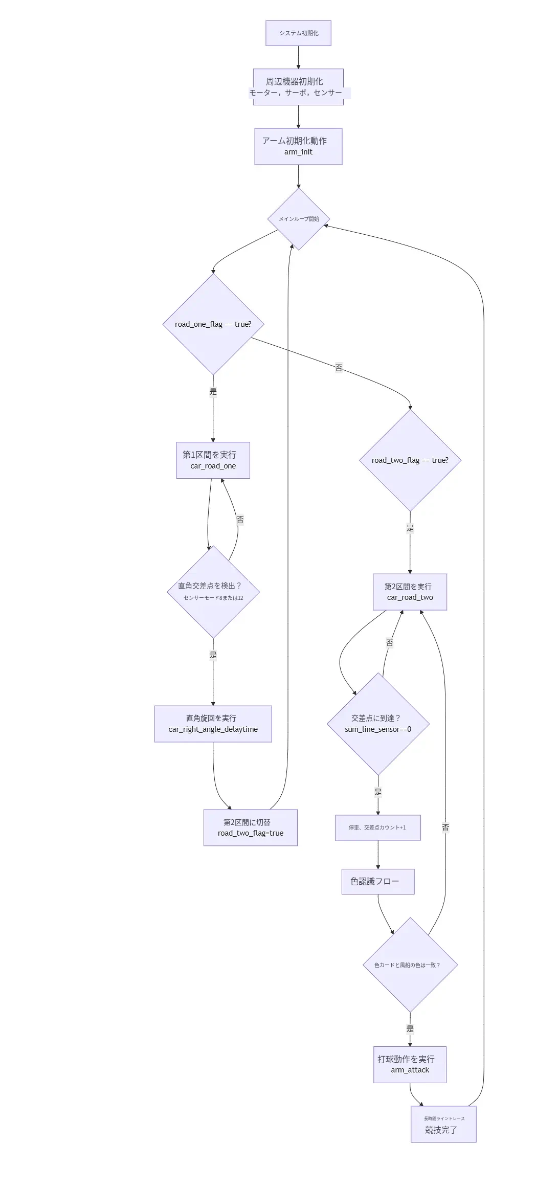
プロジェクトのダウンロード
ソースコードのリンク:(HumansX サポートより提供)
プログラムコード
コアコード:main.c
/* USER CODE BEGIN Header */
/**
  ******************************************************************************
  * @file           : main.c
  * @brief          : Main program body
  ******************************************************************************
  * @attention
  *
  * Copyright (c) 2025 STMicroelectronics.
  * All rights reserved.
  *
  * This software is licensed under terms that can be found in the LICENSE file
  * in the root directory of this software component.
  * If no LICENSE file comes with this software, it is provided AS-IS.
  *
  ******************************************************************************
  */
/* USER CODE END Header */
/* Includes ------------------------------------------------------------------*/
#include "main.h"
#include "tim.h"
#include "usart.h"
#include "gpio.h"

/* Private includes ----------------------------------------------------------*/
/* USER CODE BEGIN Includes */
#include "led.h"
#include "color.h"
#include "servo.h"
#include "motor.h"
#include "string.h"
#include "stdbool.h"
#include "line_sensor.h"
/* USER CODE END Includes */

/* Private typedef -----------------------------------------------------------*/
/* USER CODE BEGIN PTD */

/* USER CODE END PTD */

/* Private define ------------------------------------------------------------*/
/* USER CODE BEGIN PD */

/* USER CODE END PD */

/* Private macro -------------------------------------------------------------*/
/* USER CODE BEGIN PM */

/* USER CODE END PM */

/* Private variables ---------------------------------------------------------*/

/* USER CODE BEGIN PV */
int line_left_speed = 109;         //When the car is patrolling the line, the speed of the left wheel in a straight line
int line_right_speed = 109;        //When the car is patrolling along a straight line, the speed of the right wheel
int turn_left_speed = 200;         //When the car takes a right-angle route, the speed of the left wheel
int turn_right_speed = 200;        //When the car takes a right-angle route, the speed of the right wheel
uint8_t sum_line_sensor = 0;       //Record the sum of the displacement of the four line patrol sensors
bool road_one_flag = true;         //The sign position for the car to take the first route
bool road_two_flag = false;        //The sign position for the car to take the second route
uint8_t crossroads_numbers = 0;    //Record the number of intersections encountered by the car

int servo_angle_down = 135;        //Define the angle value for the downward movement of the servo motor
int servo_angle_up = 35;           //Define the angle value for the downward movement of the servo motor
int servo_angle_prepare = 50;      //Define the angle value when the servo is ready to recognize colors
uint8_t RGB_Data[3];               //Used for storing color sensor values. RGB_Data[0]: red  RGB_Data[1]: green  RGB_Data[2]: blue
int card_color = 0;                //Used for storing color card colors (Red is 1, green is 2, and blue is 3)
int ball_color = 0;                //Used for storing balloon colors (Red is 1, green is 2, and blue is 3)

void car_road_one();               //Function for the car to follow the first route segment
void car_road_two();               //Function for the car to take the second route
void right_angle_road();           //Function for a car passing through a right-angle intersection
void tracking_delaytime(uint32_t delay_time);  //Duration of the car's line-following action (time: delay_time, uint: ms)
void car_right_angle_delaytime(uint32_t delay_time);  //Duration of the car executing a right-angle intersection maneuver (time: delay_time, uint: ms)
void led_flag(uint8_t led_mode, uint8_t shine_numbers);  //Function for controlling the number of times the light on the board flashes

void arm_init();                     //servo init action
void arm_prepare_detector();         //Servo motor is ready to detect color action
void arm_attack(int attack_numbers); //The servo motor performs the action of hitting the balloon

typedef struct {
    float r_avg;
    float g_avg;
    float b_avg;
} RGB_Average;
RGB_Average color_sensor_collect(int cycles); //Execute the function to obtain the number of times the color sensor value is obtained
uint8_t get_color();                          //Obtain the color value detected by the current color sensor
/* USER CODE END PV */

/* Private function prototypes -----------------------------------------------*/
void SystemClock_Config(void);
/* USER CODE BEGIN PFP */

/* USER CODE END PFP */

/* Private user code ---------------------------------------------------------*/
/* USER CODE BEGIN 0 */

/* USER CODE END 0 */

/**
  * @brief  The application entry point.
  * @retval int
  */
int main(void)
{

  /* USER CODE BEGIN 1 */

  /* USER CODE END 1 */

  /* MCU Configuration--------------------------------------------------------*/

  /* Reset of all peripherals, Initializes the Flash interface and the Systick. */
  HAL_Init();

  /* USER CODE BEGIN Init */

  /* USER CODE END Init */

  /* Configure the system clock */
  SystemClock_Config();

  /* USER CODE BEGIN SysInit */

  /* USER CODE END SysInit */

  /* Initialize all configured peripherals */
  MX_GPIO_Init();
  MX_TIM1_Init();
  MX_USART1_UART_Init();
  MX_TIM3_Init();
  MX_TIM2_Init();
  MX_USART2_UART_Init();
  HAL_Delay(12000);
  /* USER CODE BEGIN 2 */
  Motor_Init();       //motor init
  Servo_Init();       //servo init
  arm_init();         //servo init action
  //arm_attack(3);    //servo attack action
  /* USER CODE END 2 */

  /* Infinite loop */
  /* USER CODE BEGIN WHILE */
  while (1)
  {
    /* USER CODE END WHILE */

    /* USER CODE BEGIN 3 */
    //Car executes route one
    if(road_one_flag == true){
        car_road_one();
    }

    //The car follows route two
    if(road_two_flag == true){
        car_road_two();
    }
  }
  /* USER CODE END 3 */
}

/**
  * @brief System Clock Configuration
  * @retval None
  */
void SystemClock_Config(void)
{
  RCC_OscInitTypeDef RCC_OscInitStruct = {0};
  RCC_ClkInitTypeDef RCC_ClkInitStruct = {0};

  /** Configure the main internal regulator output voltage
  */
  __HAL_RCC_PWR_CLK_ENABLE();
  __HAL_PWR_VOLTAGESCALING_CONFIG(PWR_REGULATOR_VOLTAGE_SCALE1);

  /** Initializes the RCC Oscillators according to the specified parameters
  * in the RCC_OscInitTypeDef structure.
  */
  RCC_OscInitStruct.OscillatorType = RCC_OSCILLATORTYPE_HSE;
  RCC_OscInitStruct.HSEState = RCC_HSE_ON;
  RCC_OscInitStruct.PLL.PLLState = RCC_PLL_ON;
  RCC_OscInitStruct.PLL.PLLSource = RCC_PLLSOURCE_HSE;
  RCC_OscInitStruct.PLL.PLLM = 4;
  RCC_OscInitStruct.PLL.PLLN = 84;
  RCC_OscInitStruct.PLL.PLLP = RCC_PLLP_DIV2;
  RCC_OscInitStruct.PLL.PLLQ = 4;
  if (HAL_RCC_OscConfig(&RCC_OscInitStruct) != HAL_OK)
  {
    Error_Handler();
  }

  /** Initializes the CPU, AHB and APB buses clocks
  */
  RCC_ClkInitStruct.ClockType = RCC_CLOCKTYPE_HCLK|RCC_CLOCKTYPE_SYSCLK
                              |RCC_CLOCKTYPE_PCLK1|RCC_CLOCKTYPE_PCLK2;
  RCC_ClkInitStruct.SYSCLKSource = RCC_SYSCLKSOURCE_PLLCLK;
  RCC_ClkInitStruct.AHBCLKDivider = RCC_SYSCLK_DIV1;
  RCC_ClkInitStruct.APB1CLKDivider = RCC_HCLK_DIV2;
  RCC_ClkInitStruct.APB2CLKDivider = RCC_HCLK_DIV1;

  if (HAL_RCC_ClockConfig(&RCC_ClkInitStruct, FLASH_LATENCY_2) != HAL_OK)
  {
    Error_Handler();
  }
}

/* USER CODE BEGIN 4 */
//-----------------------------------------------------------------------
//Function for the car to follow the first route segment
//The car moves from the starting area to the first right angle
void car_road_one(){
    sum_line_sensor = read_linesensor_int();
    switch(sum_line_sensor){
        case 13:
            car_move(3, 135, 135);
            break;
        case 11:
            car_move(4, 135, 135);
            break;
        //sensor1,sensor2,sensor3 trigger, sensor4 did not trigger
        case 8:
            road_one_flag = false;
            road_two_flag = true;
            break;
        //sensor1,sensor2 trigger, sensor3,sensor4 did not trigger
        case 12:
            road_one_flag = false;
            road_two_flag = true;
            break;
        default:
            car_move(1, line_right_speed, line_right_speed);
            break;
    }
    //The car passes through the first right-angle intersection
    if(road_two_flag == true){
        car_right_angle_delaytime(700);
        car_move(5, 0, 0); HAL_Delay(1000);
    }
}

//-----------------------------------------------------------------------
//Duration of the car executing a right-angle intersection maneuver (time: delay_time, uint: ms)
void car_right_angle_delaytime(uint32_t delay_time){
    uint32_t time_now = HAL_GetTick();
    while( HAL_GetTick() - time_now < delay_time){
        sum_line_sensor = read_linesensor_int();
        switch(sum_line_sensor){
            //sensor1 trigger, sensor2,sensor3,sensor4 didn't trigger
            case 14:
                car_move(3, turn_left_speed, turn_right_speed);
                break;
            //sensor1,sensor2 trigger, sensor3,sensor4 didn't trigger
            case 12:
                car_move(3, turn_left_speed * 0.8, turn_right_speed * 0.8);
                break;
            //sensor1,sensor2,sensor3 trigger, sensor4 didn't trigger
            case 8:
                car_move(3, turn_left_speed, turn_right_speed);
                break;

            //sensor4 trigger, sensor1,sensor2,sensor3 didn't trigger
            case 7:
                car_move(4, turn_left_speed, turn_right_speed);
                break;
            //sensor3,sensor4 trigger, sensor1,sensor2 didn't trigger
            case 3:
                car_move(4, turn_left_speed * 0.8, turn_right_speed * 0.8);
                break;
            case 1:
                car_move(4, turn_left_speed, turn_right_speed);
                break;
            default:
                car_move(1, line_left_speed, line_right_speed);
                break;

        }
    }
}

//-----------------------------------------------------------------------
//The car starts by passing through the first right-angle area, then detects
//the color of the color card, detects the color of the balloon, ties the balloon,
//and leaves the second right-angle route
void car_road_two(){
    sum_line_sensor = read_linesensor_int();
    switch(sum_line_sensor){
        case 0:
            car_move(5, 0, 0); HAL_Delay(1000);
            crossroads_numbers = crossroads_numbers + 1;
            if( crossroads_numbers == 1){
                //detect card color
                card_color = get_color();
                //If a red balloon is detected, the first light flashes 6 times;
                //if a green balloon is detected, the second light flashes 6 times;
                //if a blue balloon is detected, the third light flashes 6 times
                led_flag(card_color, 6);
                tracking_delaytime(920);
                car_move(5, 0, 0); HAL_Delay(1000);

                //Detect the color of the first balloon
                ball_color = get_color();
                //If the color of the color card is detected to be consistent with that of the balloon
                if(card_color == ball_color){
                    //If the color of the color card matches the color of the balloon,
                    //the servo motor executes the balloon-punching action 5 times
                    arm_attack(5);
                    //Allow the car ample time to pass through the second right-angle intersection
                    car_right_angle_delaytime(5000);
                    tracking_delaytime(150000);
                }
            }
            if( crossroads_numbers == 2){
                tracking_delaytime(920);
                car_move(5, 0, 0); HAL_Delay(1000);
                //Detect the color of the third balloon
                ball_color = get_color();
                //If a red balloon is detected, the first light flashes 6 times;
                //if a green balloon is detected, the second light flashes 6 times;
                //if a blue balloon is detected, the third light flashes 6 times
                led_flag(card_color, 6);
                //If the color of the color card is detected to be consistent with that of the balloon
                if(card_color == ball_color){
                    //If the color of the color card matches the color of the balloon,
                    //the servo motor executes the balloon-punching action 5 times
                    arm_attack(5);
                    //Allow the car ample time to pass through the second right-angle intersection
                    car_right_angle_delaytime(5000);
                    tracking_delaytime(150000);
                }
            }
            if( crossroads_numbers == 3){
                tracking_delaytime(920);
                car_move(5, 0, 0); HAL_Delay(1000);
                //Detect the color of the third balloon
                ball_color = get_color();
                //If a red balloon is detected, the first light flashes 6 times;
                //if a green balloon is detected, the second light flashes 6 times;
                //if a blue balloon is detected, the third light flashes 6 times
                led_flag(card_color, 6);
                //If the color of the color card is detected to be consistent with that of the balloon
                if(card_color == ball_color){
                    //If the color of the color card matches the color of the balloon,
                    //the servo motor executes the balloon-punching action 5 times
                    arm_attack(5);
                    //Allow the car ample time to pass through the second right-angle intersection
                    car_right_angle_delaytime(5000);
                    tracking_delaytime(150000);
                }
            }
        case 13:
            car_move(3, 135, 135);
            break;
        case 11:
            car_move(4, 135, 135);
            break;
        default:
            car_move(1, line_left_speed, line_right_speed);
            break;
    }
}

//-----------------------------------------------------------------------
//Duration of the car's line-following action (time: delay_time, uint: ms)
void tracking_delaytime(uint32_t delay_time){
    uint32_t time_now = HAL_GetTick();
    while( HAL_GetTick() - time_now < delay_time){
        sum_line_sensor = read_linesensor_int();
        switch(sum_line_sensor){
            case 13:
                car_move(3, 135, 135);
                break;
            case 11:
                car_move(4, 135, 135);
                break;
            default:
                car_move(1, line_left_speed, line_right_speed);
                break;
        }
    }
}

//-----------------------------------------------------------------------
//Function for controlling the number of times the light on the board flashes
//If a red balloon is detected, the first light flashes 6 times;
//if a green balloon is detected, the second light flashes 6 times;
//if a blue balloon is detected, the third light flashes 6 times
void led_flag(uint8_t led_mode, uint8_t shine_numbers){
    if(shine_numbers <=0){ shine_numbers = 1; }
    switch(led_mode){
        case 1:
            for(uint8_t i=0;i<shine_numbers;i++){
                led_open(1);HAL_Delay(50); led_off(1);HAL_Delay(50);
            }
            break;
        case 2:
            for(uint8_t i=0;i<shine_numbers;i++){
                led_open(2);HAL_Delay(50); led_off(2);HAL_Delay(50);
            }
            break;
        case 3:
            for(uint8_t i=0;i<shine_numbers;i++){
                led_open(3);HAL_Delay(50); led_off(3);HAL_Delay(50);
            }
            break;
        default: break;
    }
}

//-----------------------------------------------------------------------
//Servo initialization action
void arm_init(){
    servo_write270(1, servo_angle_up);
}

//-----------------------------------------------------------------------
//The servo motor performs the action of hitting the balloon
void arm_attack(int attack_numbers){
    for(int i=0;i<attack_numbers;i++){
        servo_write270(1, servo_angle_down);
        HAL_Delay(498);
        servo_write270(1, servo_angle_up);
        HAL_Delay(498);
    }
}

//-----------------------------------------------------------------------
//Servo motor is ready to detect color action
void arm_prepare_detector(){
    servo_write270(1, servo_angle_prepare);
}

//-----------------------------------------------------------------------
RGB_Average color_sensor_collect(int cycles) {
    uint8_t RGB_Data[3];
    RGB_Average result = {0, 0, 0};

    // 用于累加的变量
    unsigned long r_sum = 0;
    unsigned long g_sum = 0;
    unsigned long b_sum = 0;
    int valid_count = 0;

    for(int i = 0; i < cycles; i++) {
        uint8_t *get_color = color_read();
        memcpy(RGB_Data, get_color, sizeof(RGB_Data));

        // 检查数据是否有效(非零)
        if((RGB_Data[0] != 0) && (RGB_Data[1] != 0) && (RGB_Data[2] != 0)) {
            printf("the %d numbers - R: %d  G: %d  B: %d \r\n", i+1, RGB_Data[0], RGB_Data[1], RGB_Data[2]);

            // 累加有效数据
            r_sum += RGB_Data[0];
            g_sum += RGB_Data[1];
            b_sum += RGB_Data[2];
            valid_count++;
        } else {
            printf("the %d numbers - error num, pass\r\n", i+1);
        }

        HAL_Delay(100);
    }

    // 计算平均值
    if(valid_count > 0) {
        result.r_avg = (float)r_sum / valid_count;
        result.g_avg = (float)g_sum / valid_count;
        result.b_avg = (float)b_sum / valid_count;
    }

    printf("finish youxiaocishu: %d/%d\r\n", valid_count, cycles);
    printf("average - R: %.2f  G: %.2f  B: %.2f\r\n", result.r_avg, result.g_avg, result.b_avg);

    return result;
}

//-----------------------------------------------------------------------
uint8_t get_color(){
    arm_prepare_detector();
    HAL_Delay(800);
    uint8_t color_flag = 0;
    RGB_Average avg = color_sensor_collect(10);

    printf("average red: %.2f\n", avg.r_avg);
    printf("average green: %.2f\n", avg.g_avg);
    printf("average blue: %.2f\n", avg.b_avg);

    if( (avg.r_avg >= 14) && (avg.r_avg >= avg.g_avg) && (avg.r_avg >= avg.b_avg) ){ //14
        color_flag = 1;
    }

    if( (avg.g_avg >= 15) && (avg.g_avg >= avg.r_avg) && (avg.g_avg >= avg.b_avg) ){ //15
        color_flag = 2;
    }

    if( (avg.b_avg >= 15) && (avg.b_avg >= avg.r_avg) && (avg.b_avg >= avg.g_avg) ){ //15
        color_flag = 3;
    }
    arm_init();
    HAL_Delay(1000);
    return color_flag;
}

/* USER CODE END 4 */

/**
  * @brief  This function is executed in case of error occurrence.
  * @retval None
  */
void Error_Handler(void)
{
  /* USER CODE BEGIN Error_Handler_Debug */
  /* User can add his own implementation to report the HAL error return state */
  __disable_irq();
  while (1)
  {
  }
  /* USER CODE END Error_Handler_Debug */
}

#ifdef  USE_FULL_ASSERT
/**
  * @brief  Reports the name of the source file and the source line number
  *         where the assert_param error has occurred.
  * @param  file: pointer to the source file name
  * @param  line: assert_param error line source number
  * @retval None
  */
void assert_failed(uint8_t *file, uint32_t line)
{
  /* USER CODE BEGIN 6 */
  /* User can add his own implementation to report the file name and line number,
     ex: printf("Wrong parameters value: file %s on line %d\r\n", file, line) */
  /* USER CODE END 6 */
}
#endif /* USE_FULL_ASSERT */
操作手順:
全体の流れ:
(1) STM32CubeMX ソフトウェアでピン割り当てと周辺機能の初期化を行い、設定コードを生成します。
(2) keil5 で MDK_ARM プロジェクトファイルを開き、コードの編集・コンパイル・デバッグを行います。
基本パラメータ:
本ドキュメントの(ハードウェアモジュール)に従って開発環境を構築した後の基本パラメータは次のとおりです。
ソフトウェアバージョン:STM32CubeMX V6.14.0
ハードウェアプラットフォーム:STM32F407IGT6
コンパイル環境:MDK_ARM V5.3.2
デバッグツール:ST-LINK/V2
1. 新規プロジェクトの作成と MCU の設定
1.1 MCU の選択
- STM32CubeMX ソフトウェアを開き、File > New Project をクリックします。

2. MCU の絞り込み条件を設定して STM32F407IGT6 を選択し、バージョン欄をクリックして、最後に Start Project をクリックしてプロジェクトの設定を開始します。
- プロジェクト設定画面は次のとおりです。
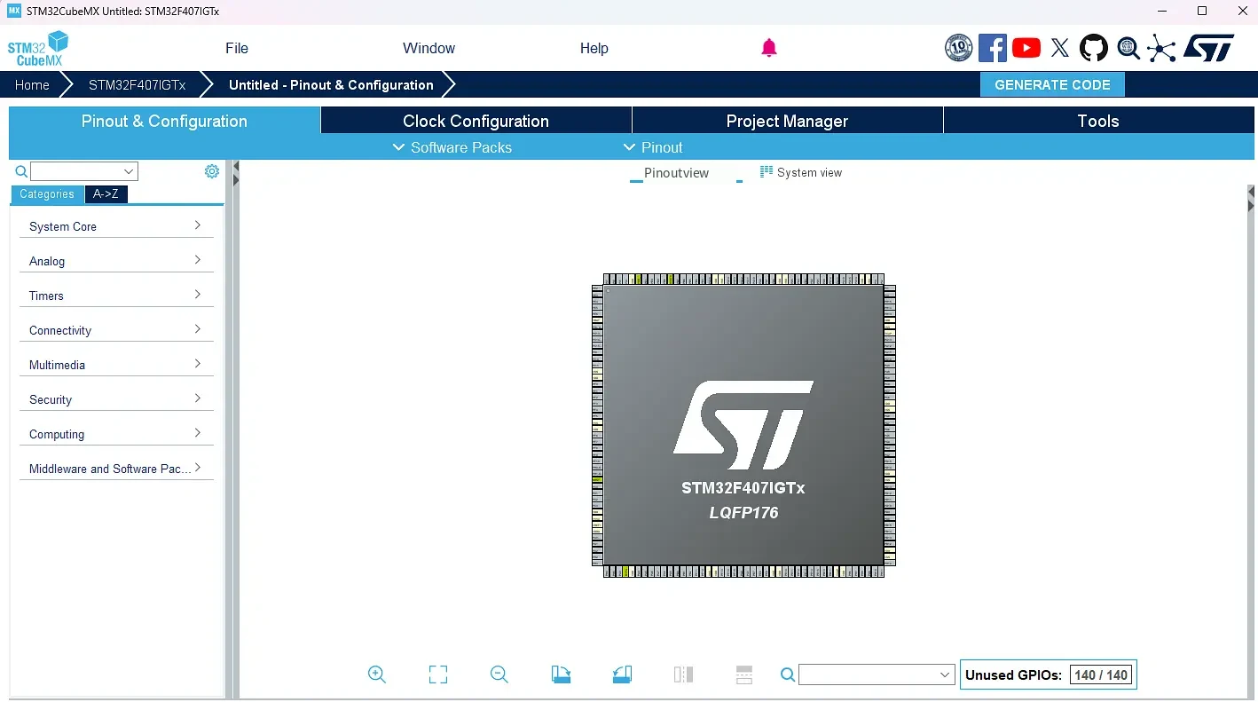
1.2 クロック設定とコア設定
- Pinout & Configuration の System Core で RCC(リセットおよびクロック制御) をクリックします。
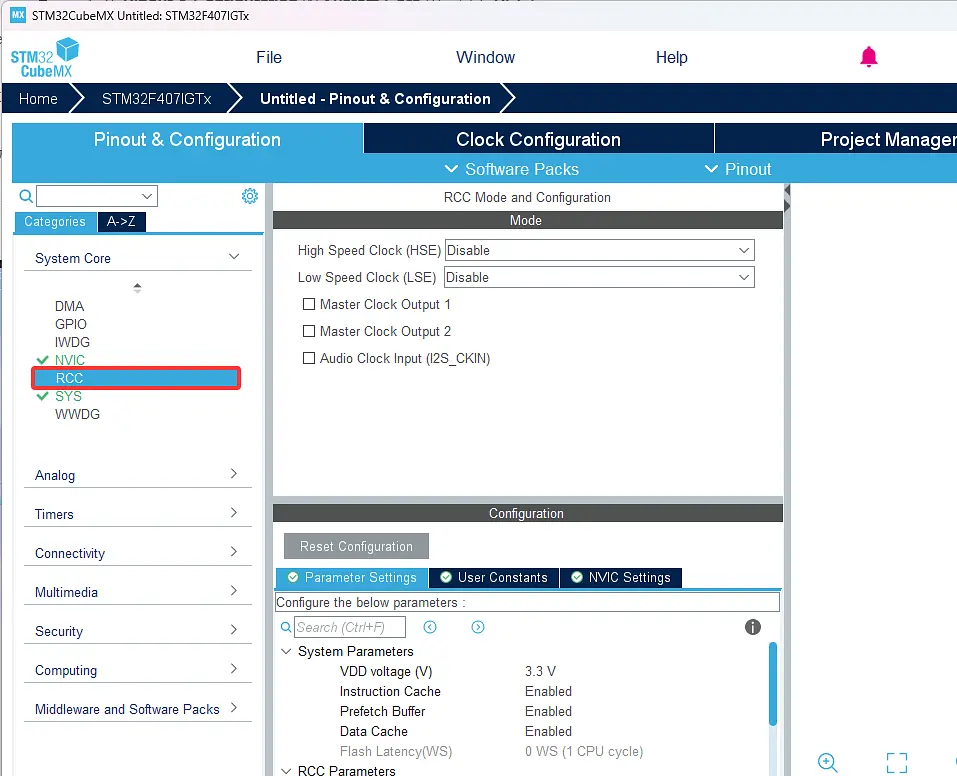
- HSE クロックソースを Crystal/Ceramic Resonator(水晶またはセラミック発振子)に設定します。
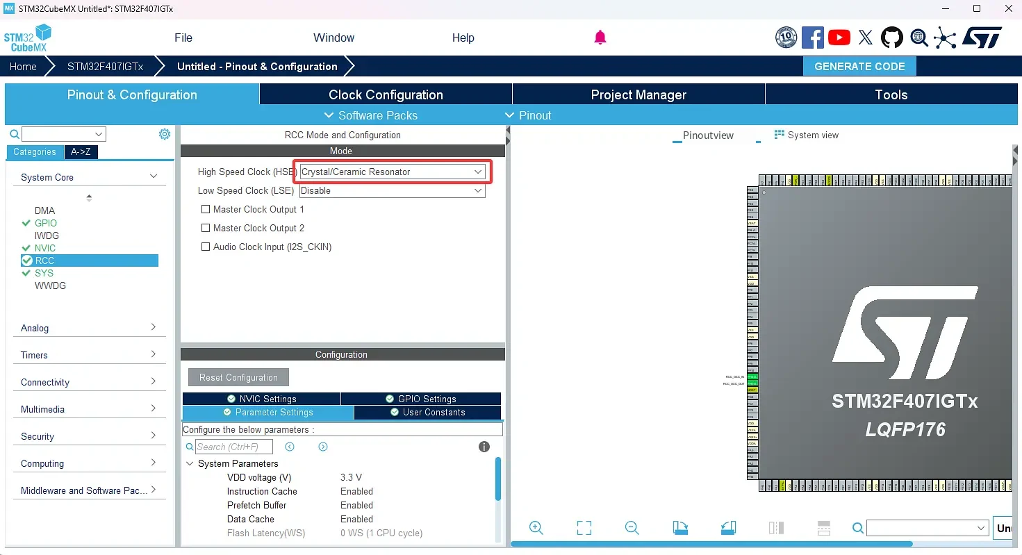
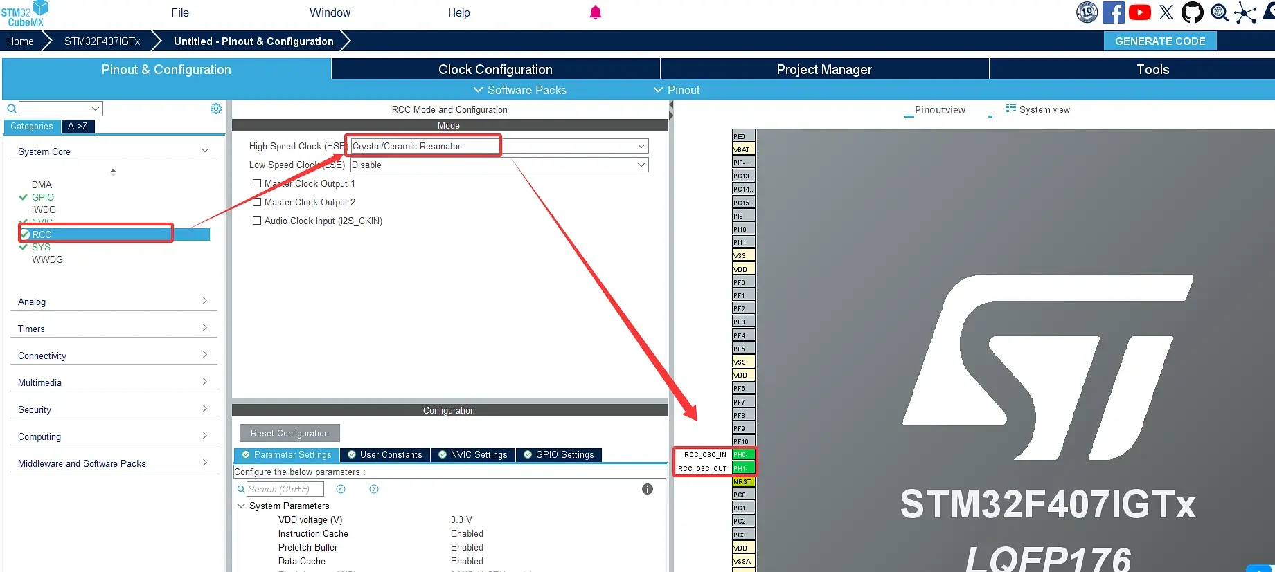
- 設定が完了すると、対応するピン(OSC_IN と OSC_OUT)が自動的に設定されます(下図の緑色の部分を参照)。
機能:
- 外部高速水晶発振器(HSE)を接続し、システムに高精度なクロック源を供給します。
**RCC_OSC_IN**:水晶入力ピン。**RCC_OSC_OUT**:水晶出力ピン(帰還信号)。- デフォルトの機能:
**PH0**:**OSC_IN**(外部水晶入力)。**PH1**:**OSC_OUT**(外部水晶出力)。
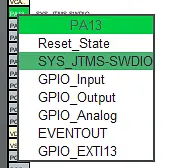
- デバッグインターフェースのピンを設定します。System Core で SYS をクリックし、Debug のモードを Serial Wire に設定します。
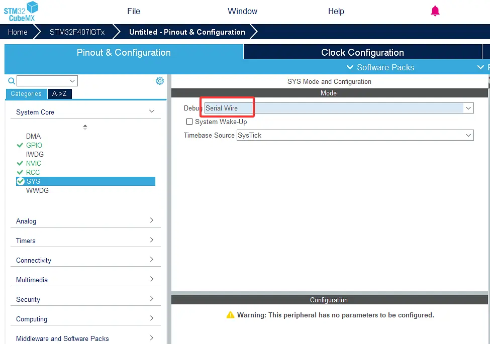
設定が完了すると、対応するピン(ピンアウト)が緑色になります。
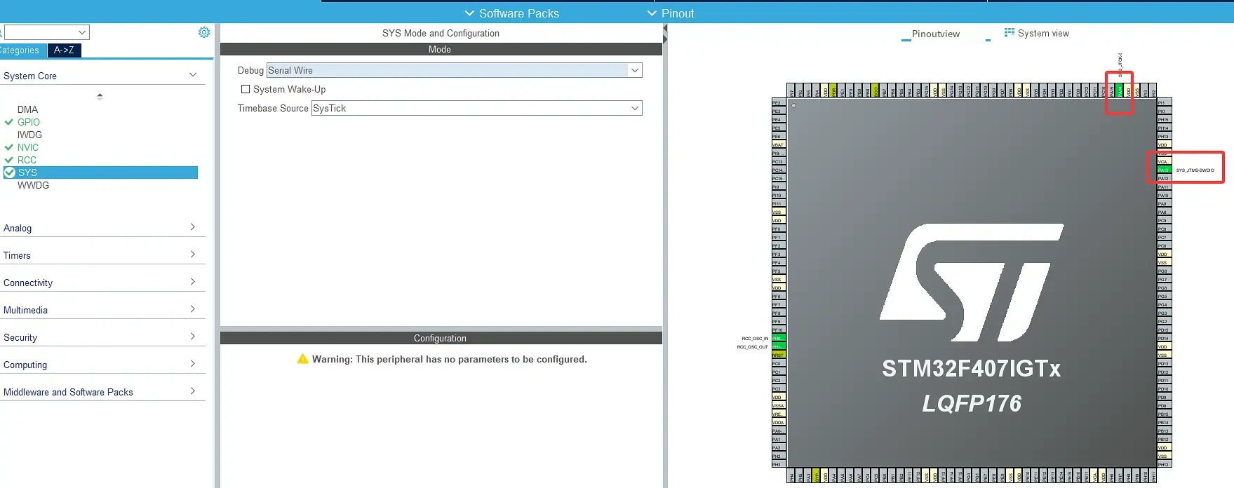
緑色の部分をクリックすると、具体的な内容を確認できます。

1.3 クロックツリーの設定
クロックパラメータを順に設定します:1. 入力周波数の値を 8 に変更、2. HSE を選択、3. PLLCLK を選択、4. HCLK のパラメータを 84 に変更。その他のパラメータはデフォルトのままで構いません。
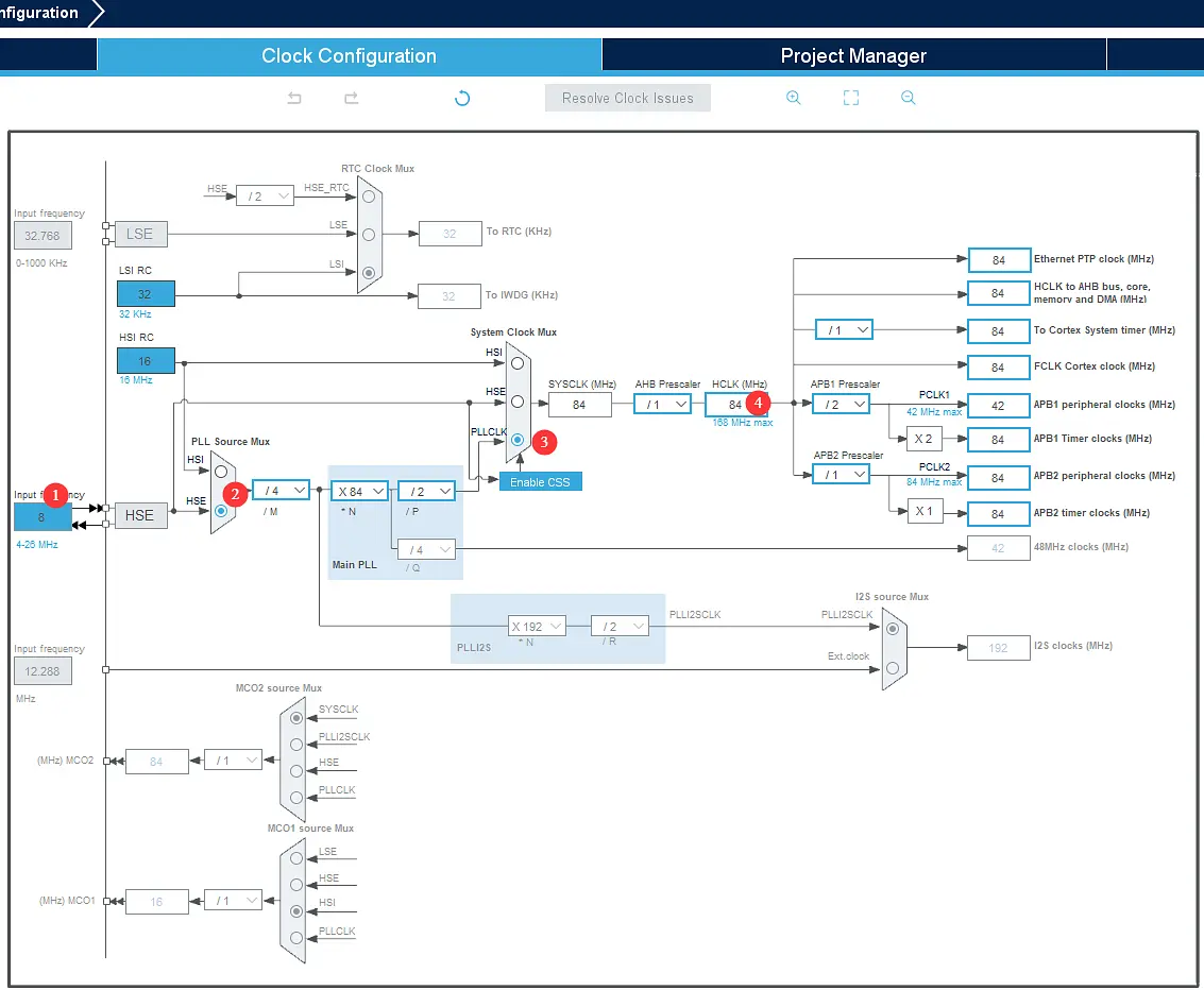
ヒント:設定時にはエラーが自動的にチェックされます。周波数の設定が誤っている場合は、赤色でエラーが表示されます。
2. MCU の初期化パラメータの設定
2.1 USART シリアルポートの設定
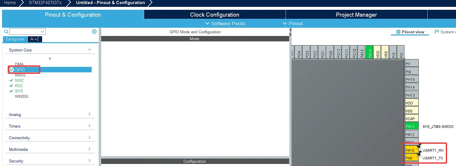
- PA9 と PA10 をそれぞれ USART1_TX と USART1_RX に設定します。GPIO をクリックしてピンを設定します(この時点では USART1 が未設定のため、ピンに黄色の警告が表示されます)。
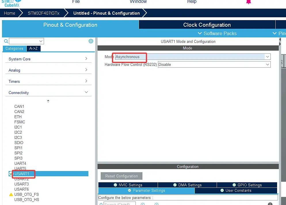
- Connectivity → USART1 をクリックし、モードを Asynchronous に設定します(USART1 を設定すると関連ピンが緑色になり、ピン設定が正常であることを示します)。
2.2 プロジェクト管理の設定
- デフォルトの画面は次のとおりです。
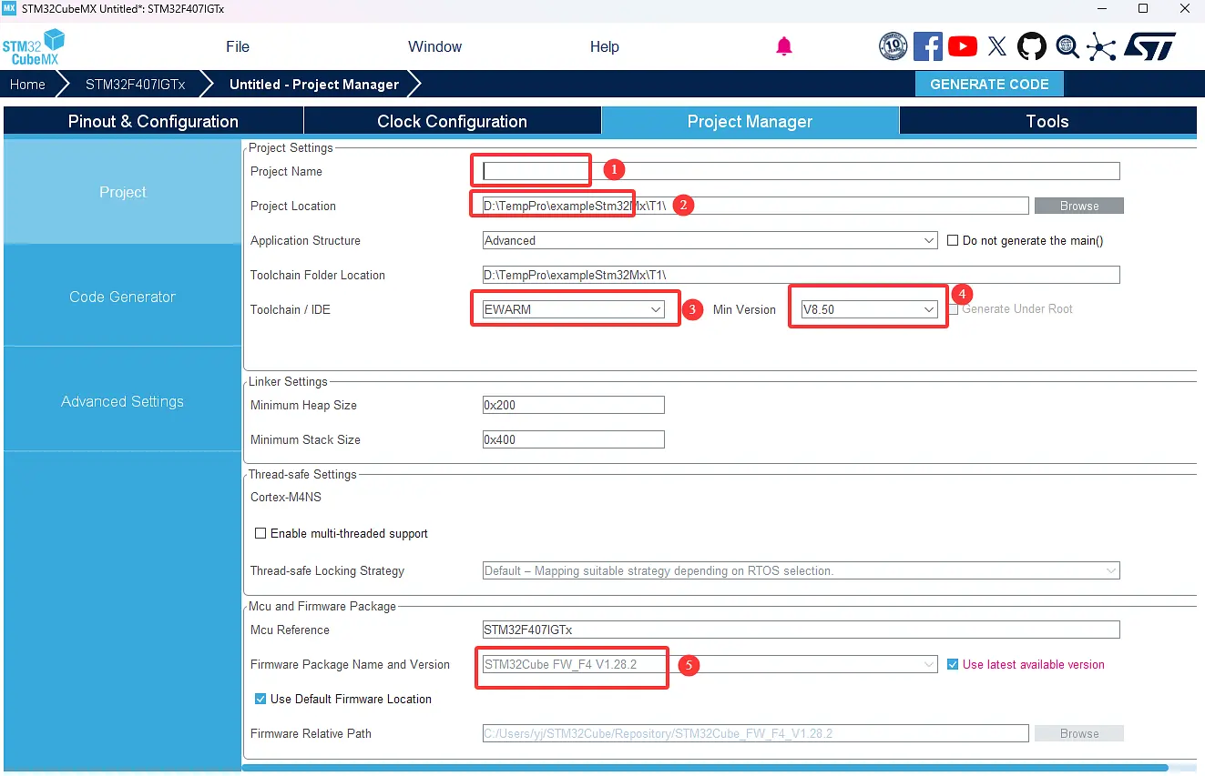
プロジェクト名を入力します(任意の名前で構いません)。
プロジェクトの保存先を選択します(C ドライブには保存しないでください)。
コンパイル環境として MDK_ARM を選択します。
バージョン番号 V5.3.2 を選択します。
ファームウェアパッケージ名とバージョン。
(ヒント:デフォルトでは Use latest available version にチェックが入っています。ただし、ローカル PC に最新バージョンがない場合はエラーになります。その場合はパッケージを各自ダウンロードしてローカルにインストールする必要があります。インストール方法は以下のリンクを参照してください。
UNI-STM32 開発環境の設定【V2.0】(リンク先の「6. よくある設定の Q&A」の Q3 に解決方法があります)
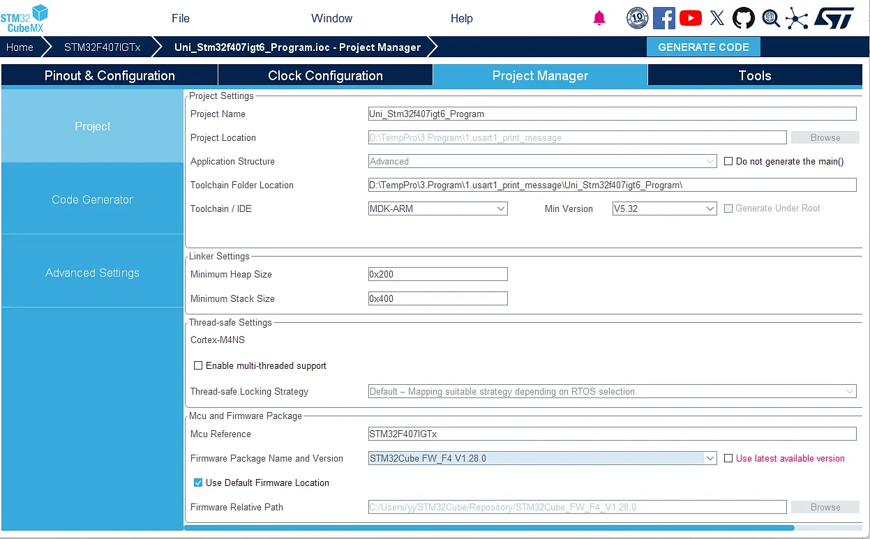
上記の設定が完了すると、下図のようになります。
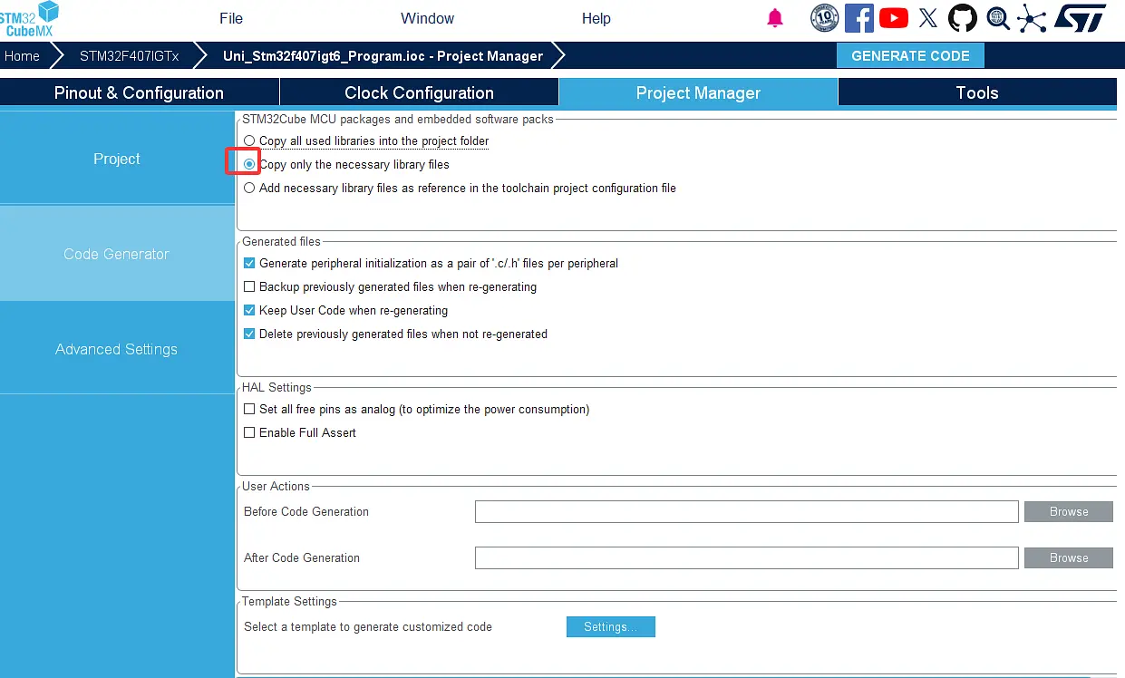
2. Project Manager > Code Generator ウィンドウを次のように設定します。
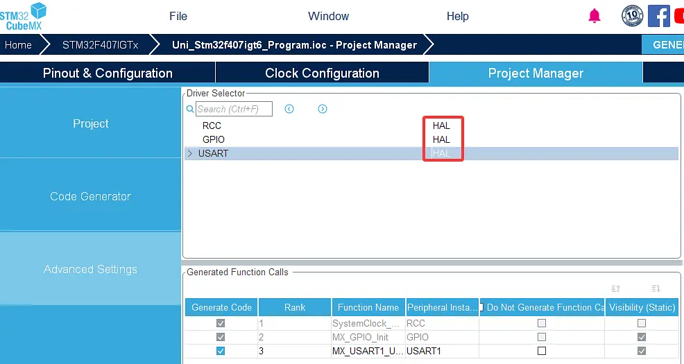
3. Project Manager > Advanced Settings ウィンドウで HAL ライブラリを選択します。
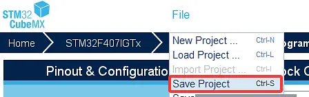
- プロジェクトを保存します:File → Save Project をクリックします。
3. GPIO の設定 ― 電子ハードウェアのパラメータ
M1 DC モーターのピンパラメータ表(PWM)
| ピン | パラメータ |
|---|---|
| PE13 | TIM1_CH3 |
| PE14 | TIM1_CH4 |
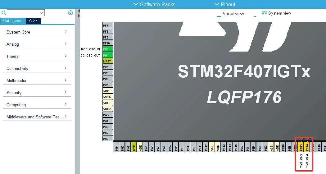
- GPIO をクリックし、PE13、PE14 ピンを探します。
ピン配置図で PE13 を左クリックし、PE13 の機能として TIM1_CH3 を選択します。同様に PE14 を左クリックし、機能として TIM1_CH4 を選択します。詳細は下図を参照してください。(注:ピン割り当てが完了するとピンはオレンジ色になります。これはピンの割り当てのみが完了し、対応する周辺機能がまだ有効化されていないことを示します。)
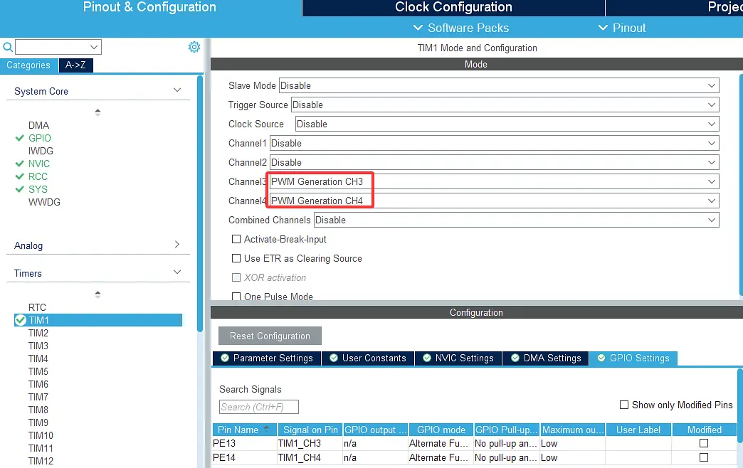
- 左側の Timers パネルをクリックし、TIM1 を選択してパラメータを設定します。
- Channel3:PWM Generation CH3
- Channel4(チャネル 4):PWM Generation CH4
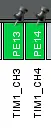
この時点でピンが緑色に変わり、正常に設定が完了したことを示します。
M2 DC モーターのピンパラメータ表(PWM)
| モーター | ピン | パラメータ |
|---|---|---|
| M2 | PB0 | TIM3_CH3 |
| PB1 | TIM3_CH4 |
- M1 の設定方法を参考に、M2 モーターのパラメータ設定を完了します。
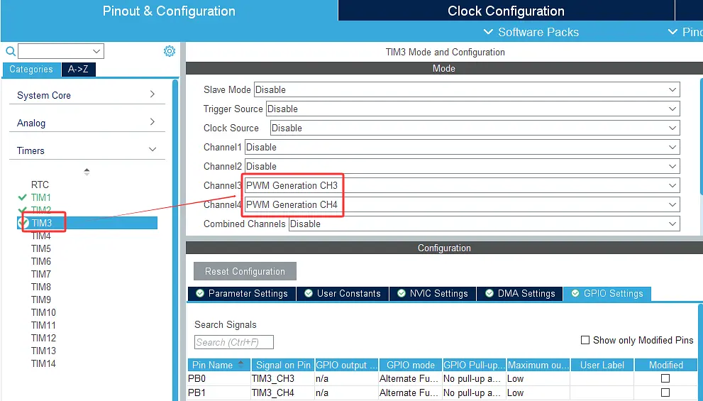
サーボのピンパラメータ表
サーボのパラメータ
| ピン | タイマー | ユーザーラベル |
|---|---|---|
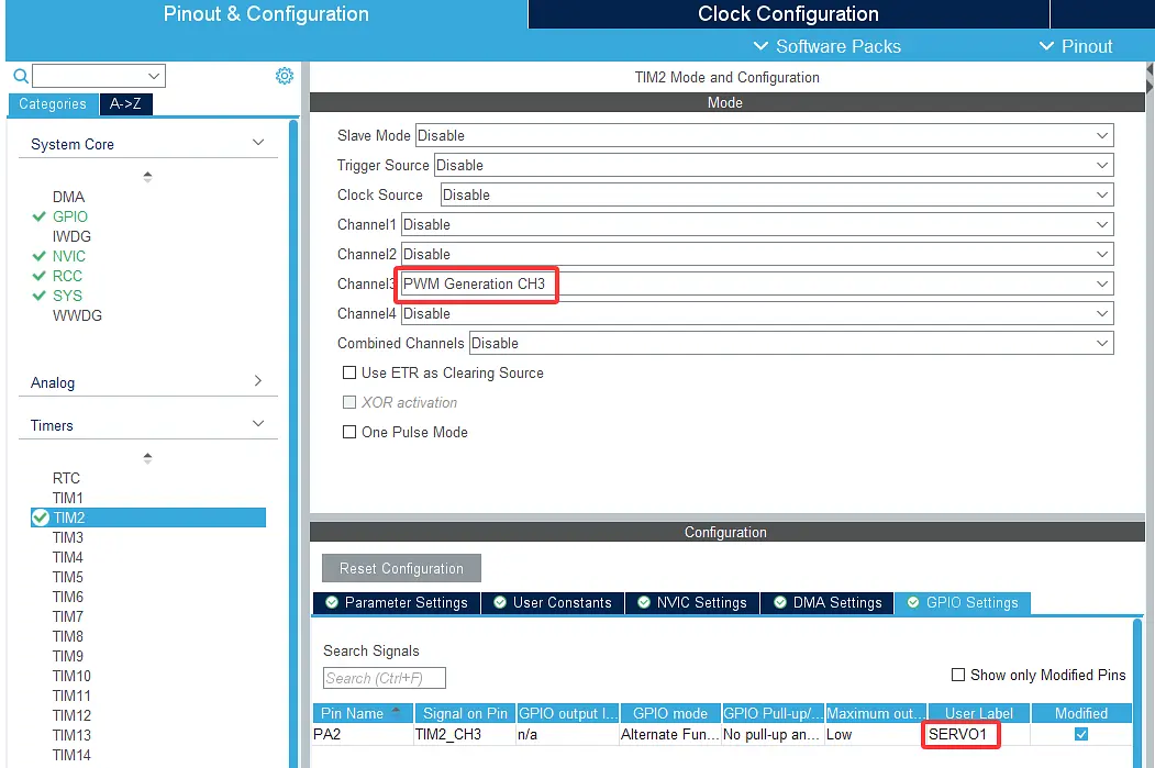
| PA2 | TIM2_CH3 | SERVO1 |
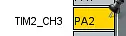
- GPIO をクリックしてピン PA2 を探します。PA2 を左クリックし、TIM2_CH3 を選択します。(注:ピン割り当てが完了するとピンはオレンジ色になります。これはピンの割り当てのみが完了し、対応する周辺機能がまだ有効化されていないことを示します。)
- Timers パネルをクリックして TIM2 を選択し、Channel3 のドロップダウンから PWM Generation CH3 を選択します。GPIO Settings を左クリックし、PA2 の行をダブルクリックして User Label を SERVO1 に設定します。
ピンが緑色に変わったことを確認します。これは正常に設定が完了したことを示します。
ライントレースモジュールのピンパラメータ表
| ピン | 機能 |
|---|---|
| PC2 | Input |
| PC3 | Input |
| PC4 | Input |
| PC5 | Input |
- PC2 ピンの設定
(1) GPIO をクリックし、Pinout view 画面下部で PC2 を検索すると、ピンビュー上の PC2 が点滅します。PC2 を左クリックし、GPIO_Input を選択します。
| 列 1 | 列 2 |
|---|---|
(2) PC2 の行をダブルクリックし、GPIO Pull-up/Pull-down の項目でドロップダウンリストから Pull-up を選択します。

図中の設定の意味
- Pull-up:該当ピンの内部プルアップ抵抗を有効にし、デフォルトでハイレベルになります。
- Pull-down:内部プルダウン抵抗を有効にし、デフォルトでローレベルになります。
- No pull-up/pull-down:プルアップ/プルダウンを無効にします。安定したレベルを確保するには外部回路が必要です。
- 同様の方法で PC3、PC4、PC5 のピン設定を完了します。最終的な結果は次のとおりです。
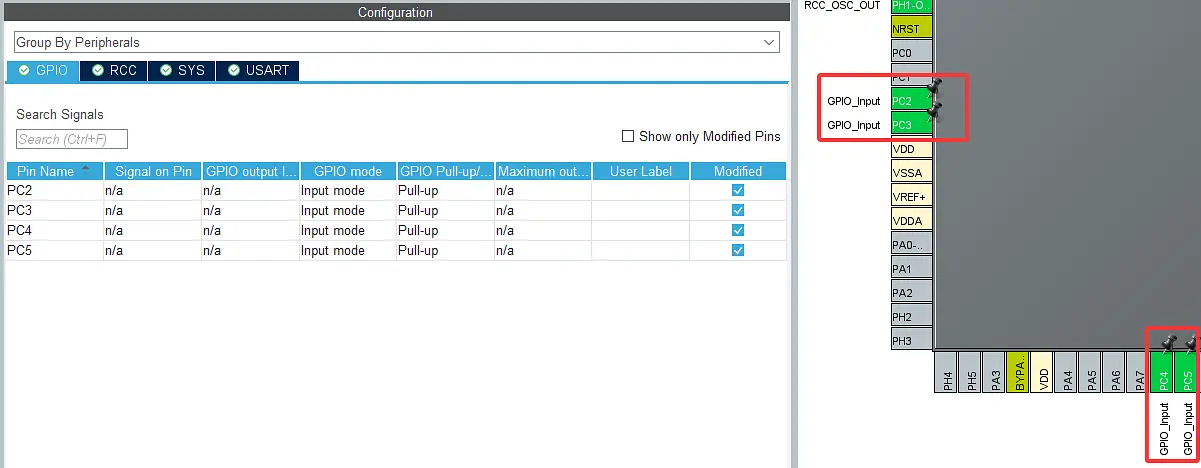
色認識センサーのピンパラメータ表
ヒント:USART2 は STM32 メインボードと色認識モジュール間の通信インターフェース、USART1 は STM32 メインボードと PC 間の通信インターフェースです。
| ピン | 機能 |
|---|---|
| PD5 | USART2_TX |
| PD6 | USART2_RX |
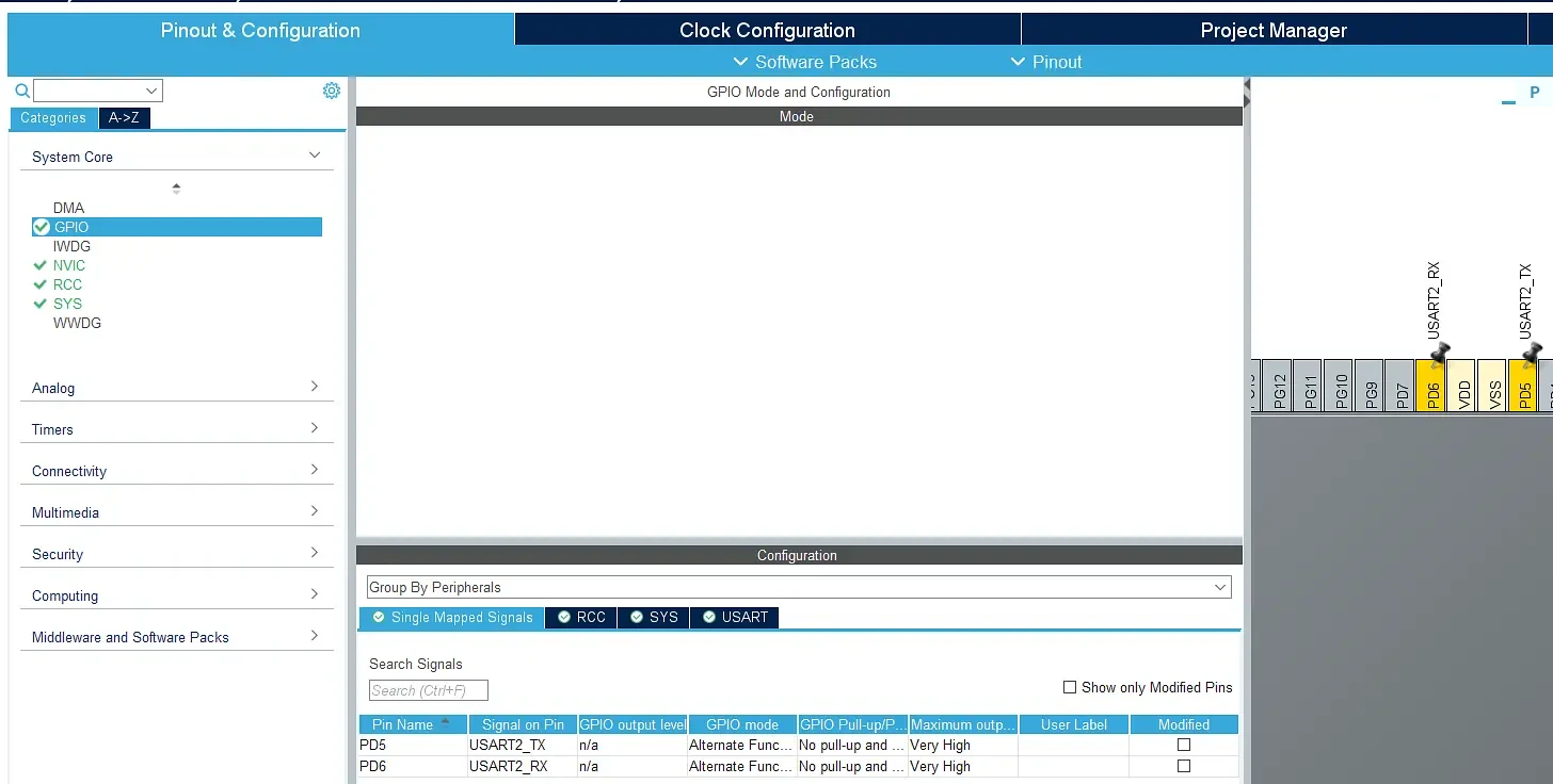
(1) GPIO をクリックし、Pinout view 画面下部で PD5 を検索すると、対応するピンが点滅します。点滅しているピンを左クリックして USART2_TX を選択します。続いて PD6 を検索し、点滅しているピンを左クリックして USART2_RX を選択します。(この時点では USART2 が未設定のため、ピンに黄色の警告が表示されます。)
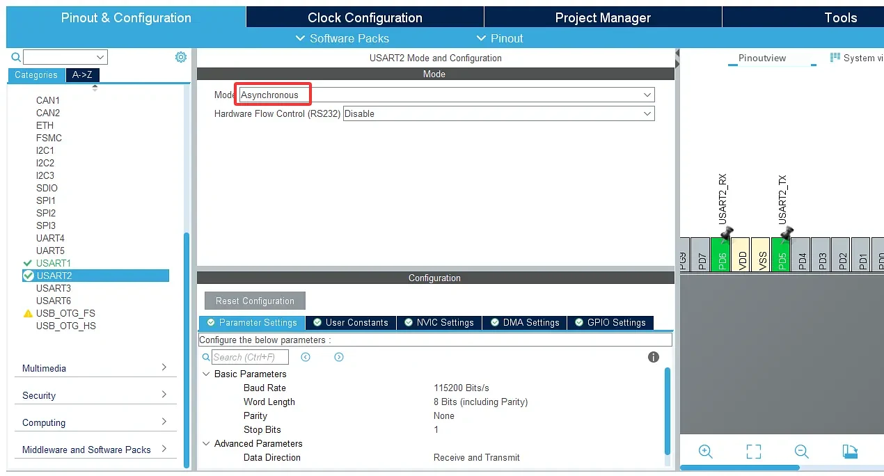
(2) Connectivity → USART2 をクリックし、モードを Asynchronous に設定します(USART2 を設定すると関連ピンが緑色になり、ピン設定が正常であることを示します)。
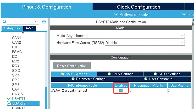
(3) USART2 の割り込みを Enabled に設定します(チェックを入れます)。
(4) GPIO Settings パネルをクリックし、PD5 の行をダブルクリックして、GPIO Pull-up/Pull-down の項目でドロップダウンリストから Pull-up を選択します。同様に PD6 の行をダブルクリックし、GPIO Pull-up/Pull-down の項目でドロップダウンリストから Pull-up を選択します。
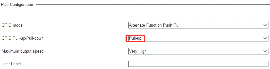
図中の設定の意味
- Pull-up:該当ピンの内部プルアップ抵抗を有効にし、デフォルトでハイレベルになります。
- Pull-down:内部プルダウン抵抗を有効にし、デフォルトでローレベルになります。
- No pull-up/pull-down:プルアップ/プルダウンを無効にします。安定したレベルを確保するには外部回路が必要です。
設定完了後の状態は下図のとおりです。

STM32 開発ボード搭載の LED ランプ 3 個のパラメータ表
| ピン | 機能 |
|---|---|
| PF13 | Output |
| PF14 | Output |
| PF15 | Output |
- PF13 ピンの設定
(1) GPIO をクリックし、Pinout view 画面下部で PF13 を検索すると、ピンビュー上の PF13 が点滅します。PF13 を左クリックし、GPIO_Output を選択します。
| 列 1 | 列 2 |
|---|---|
(2) PF13 の行をダブルクリックし、GPIO mode の項目でドロップダウンリストから Output Push Pull を選択します。
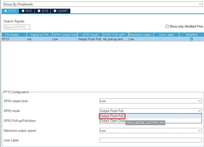
GPIO mode パラメータの補足:
| 設定項目 | 日本語名 | 特徴 |
|---|---|---|
| Output Push Pull | プッシュプル出力 | ハイ・ローともに駆動能力が高く、デフォルトの出力モードです |
| Output Open Drain | オープンドレイン出力 | ローまたはハイインピーダンス状態のみ出力でき、ハイレベルを出力するには外部プルアップ抵抗が必要です |
(3) GPIO Pull-up/Pull-down の項目でドロップダウンリストから No pull-up/pull-down を選択します。
GPIO Pull-up/Pull-down の図中の設定の意味
- Pull-up:該当ピンの内部プルアップ抵抗を有効にし、デフォルトでハイレベルになります。
- Pull-down:内部プルダウン抵抗を有効にし、デフォルトでローレベルになります。
- No pull-up/pull-down:プルアップ/プルダウンを無効にします。安定したレベルを確保するには外部回路が必要です。
(4) パラメータ設定後の状態は下図のとおりです。
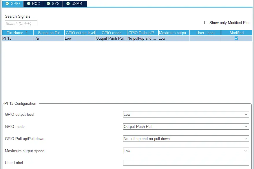
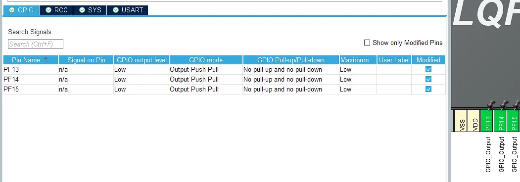
- 同様の方法で PF14、PF15 のピン設定を完了します。最終的な結果は次のとおりです。
- プロジェクトファイルを再度保存します。
ヒント:必ずプロジェクトファイルを再度保存してください(主にパラメータを保存するためです)。File → Save Project をクリックします。
4. コードの生成
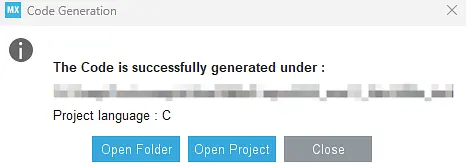
1. GENERATE CODE をクリックしてコードを生成します。
- コードが自動生成されます。
コードの生成が成功しました。


5. ユーザーコードの追加
上記で生成したフレームワークをもとに、keil エディタでユーザーコードを追加し、コンパイルとデバッグを行います。
ヒント 1:たとえば main.c の /* USER CODE BEGIN xx */ と /* USER CODE END xx */ の間にユーザーコードを追加します。
ヒント 2:独自の .c ファイルを作成することもできます。
ヒント 3:ユーザーコードは自分で記述しても構いません。(コード解説)に掲載されているサンプルを参考に学習することもできます。
6. コードのダウンロードとテスト
(1) プロジェクトをダウンロードします。デモを用意しています(本ドキュメントの「ソフトウェア設計 ― プロジェクトのダウンロード」から直接ダウンロードできます)。
書き込み方法は参考リンク(UNI-STM32 開発環境の設定【V2.0】 の「5. プログラムのダウンロード」)を参照してください。
(2) メインボードのスイッチをオンにし、動作を確認します。
実験結果
ロボットがライントレースで走行し、色を認識し、最後にロボットアームでボールを打ちます。ロボットはラインに沿って走行し、交差点(4 つのライントレースセンサーがすべて反応した状態)に来ると停止して色を認識します。次の交差点でも引き続き色を認識し、最後にロボットアームで打撃動作を模擬します。
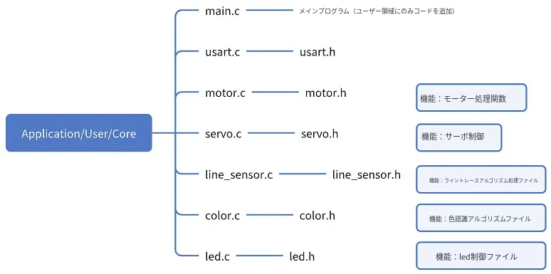
コード解説
1. ユーザーコードの解説
下図は、プロジェクトファイルに追加したユーザーコードです。
2. ユーザーコードの取り込み方法
1 つ目の方法は、ユーザー定義ファイル(.c や .h など)を自分のプロジェクトフォルダに取り込み、keil5 IDE で .c ファイルを追加してコンパイルする方法です。
既存のユーザーファイルの取り込み:keil で既存のユーザーファイルを取り込む方法 を参照してください。
2 つ目の方法は、main.c ファイルにユーザーコードを追加する方法です。
(1) まず参照用プロジェクトのコードを開きます。main.c ファイルは主に STM32CubeMX によって自動生成されたもので、このフレームワークをもとに実装したい機能を補完・改良しています。詳細は /* USER CODE BEGIN xx */ で始まり /* USER CODE END xx */ で終わる間のコードを参照してください。
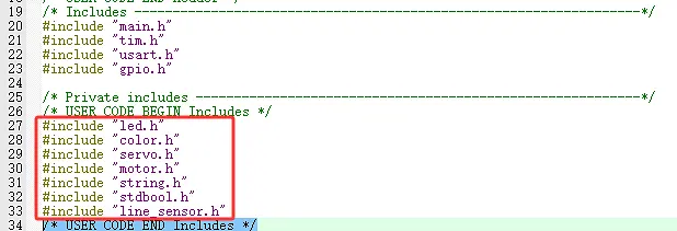


その他のユーザーコードは、/* USER CODE BEGIN で検索して追加していくことができます。
(2) ユーザーコードを自分のプロジェクトファイル main.c にコピーし、コンパイルとダウンロードを行って動作を確認します。
技術サポート
資料のダウンロード・技術サポートについては、HumansX株式会社までお問い合わせください。