 ドキュメント
実験3:二輪自立バランスカーのカスケード(角度+速度)PID制御
実験の目的
- PIDの基本原理を理解し、モーターの速度ループと角度ループの制御を実現します。2. 二輪車のバランス制御の実現方法を習得します。
PIDの基本原理:
PIDコントローラは、産業用制御システムで広く使用されているフィードバック制御器です。その名称は、比例(P)、積分(I)、微分(D)という3つの基本的な制御機能に由来しています。以下にPID制御の基本原理を示します。
- PIDコントローラの構成
比例制御(P):現在の誤差(設定値と実測値の差)に基づいて制御します。比例制御には誤差を小さくする働きがありますが、定常偏差が残る場合があります。
式:

積分制御(I):過去の誤差の累積に基づいて制御します。積分制御には定常偏差を解消する働きがありますが、システムの応答が遅くなる場合があります。
式:

微分制御(D):誤差の変化率に基づいて制御します。微分制御は将来の誤差の変化を予測し、システムの応答速度を向上させる働きがあります。
式:

- PIDコントローラの出力
PIDコントローラの総出力は、これら3つの成分の和になります。

機能要件
二輪車の自立バランスを実現します。
ハードウェアの準備
Arduino mega2560 メインボード * 1、uni mega2560 拡張ボード * 1、USBケーブル(Type-B)* 1、3S電池ボックス * 1、リチウム電池 * 3、エンコーダ付きモーター 30*2、エンコーダモーターケーブル(2.0→2.54)*2
試作構成
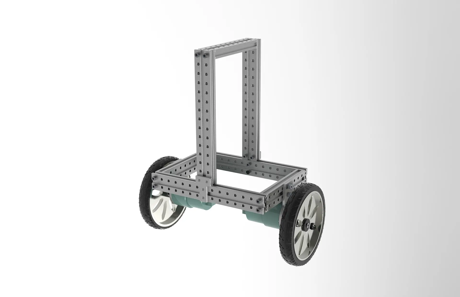
回路接続
ハードウェアモジュール
ヒント:ハードウェアモジュールの使用説明
Uni Mega2560 拡張ボード ユーザーガイド[V1.1]
ピン配置
| シャーシ | mega2560 拡張ボード |
|---|---|
| 車体の左前輪 | M1 |
| 車体の右前輪 | M2 |
| ジャイロスコープ | mega2560 拡張ボード |
| 5V | 5V |
| SDA | SCL |
| SCL | SDA |
| GND | GND |
実機配線
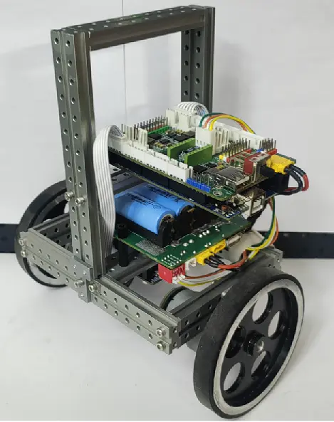
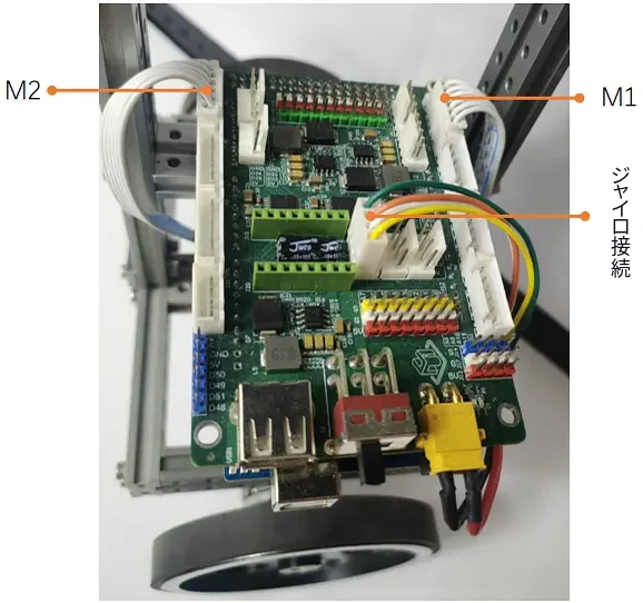
ソフトウェア設計
ソースコードとライブラリのダウンロード
ソースコードリンク:(HumansX サポートより提供) AE /3.PID%E5%BC%80%E6%BA%90%E9%A1%B9%E7%9B% AE /7.%E5%8F%8C%E8%BD% AE %E8%87%AA%E5%B9%B3%E8%A1%A1%E5%B0%8F%E8%BD%A6%E4%B8%B2%E7%BA%A7%EF%BC%88%E8%A7%92%E5%BA%A6+%E9%80%9F%E5%BA%A6%EF%BC%89PID%E6%8E%A7%E5%88%B6
ライブラリリンク:(HumansX サポートより提供)
ライブラリファイルのインポート
インポートが必要なライブラリ:Unirobot_Mega_V1.2
プログラムコード
具体的なコード:
example.ino がメインプログラムです。プロジェクトの完全なコードは(ソースコードリンク)からダウンロードしてください。
/************************************************************
-----------<Uni自平衡小车>-----------
日期:2025.08.18
*************************************************************/
#include <KalmanFilter.h>    //卡尔曼滤波
#include "Wire.h"            //调用IIC底层库
#include "I2Cdev.h"          //定义IIC设备数据
#include "MPU6050_6Axis_MotionApps20.h"//MPU6050库文件
#define  RATE  115200 //设定Mega2560开发板串口波特率为115200

MPU6050 Mpu6050;             //声明陀螺仪模块
KalmanFilter KalFilter;      //声明卡尔曼滤波对象

//定义陀螺仪pid参数
// float Balance_Kp=300.0,Balance_Kd=20.0;
// float Balance_Kp=0.0, Balance_Kd=0.0;
float Balance_Kp=40.0, Balance_Kd=0.6;
// float Balance_Kp=15.0, Balance_Kd=0.4;
//定义编码电机速度环pid参数
// float Velocity_Kp=0.4,Velocity_Ki=0.4/200.0;
float Velocity_Kp=0.6;
float Velocity_Ki=Velocity_Kp/200.0;

// 卡尔曼滤波参数
int16_t ax, ay, az, gx, gy, gz;
float K1 = 0.05, Q_angle = 0.001, Q_gyro = 0.005;
float R_angle = 0.5 , C_0 = 1, dt = 0.005;
//定义小车编码电机相关参数
int motor_pwm_limit = 200; //定义编码电机pwm模式速度上限
float target_speed = 0;  //用于串口调试轮子pid参数
int Motor1, Motor2; //用于存储小车双轮最终计算得到的pwm值
int Balance_Pwm, Velocity_Pwm, Turn_Pwm;//用于存储陀螺仪-速度-转向环的pwm值
int Velocity_Left, Velocity_Right = 0; //用于存储小车左轮,右轮Δ时间内的编码差值
volatile long Velocity_L, Velocity_R = 0; //用于存储小车左轮,右轮Δ时间内的编码差值

int car_stop_flag = 59; //设定编码电机安全范围。当陀螺仪倾斜超过car_stop_flag度时,小车停止
long last_encoder_left, last_encoder_right; //用于存储小车双轮上一次的编码值
float car_mechanical_median = -0.2; //设定小车机械结构的物理结构中值(需要通过陀螺仪数据确认)

void setup() {
  delay(2000);          //开机等待2秒
  Serial.begin(RATE);   //设置串口波特率
  motor_init();         //电机引脚初始化
  Wire.begin();         //启动IIC总线
  Mpu6050.initialize(); //陀螺仪模块初始化
  delay(20);            //程序等待20毫秒.
}

void loop() {
  control();            //启动自平衡小车程序
  delay(5);             //设定自平衡小车控制周期
}
/**************************************************************************
入口参数:角度、角速度
返回  值:直立控制PWM
**************************************************************************/
int balance(float Angle, float Gyro)
{
  float Bias;
  int balance;
  Bias = Angle - car_mechanical_median;   //===求出平衡的角度中值 和机械相关
  balance = Balance_Kp * Bias + Gyro * Balance_Kd; //===计算平衡控制的电机PWM  PD控制   kp是P系数 kd是D系数
  return balance;
}
//小车双轮驱动程序部分
#include "uni_motor.h" //调用编码电机控制库函数
UNI_MOTOR motor1(1);   //声明小车左轮编码电机模块
UNI_MOTOR motor2(2);   //声明小车右轮编码电机模块

/*********************
电机引脚初始化
*********************/
void motor_init(){
  motor1.init();  //编码电机motor1初始化参数设置
  motor2.init();  //编码电机motor2初始化参数设置
  motor1.set_parameters(13, 30, 0.0475); //设置编码电机线圈数,减速比,电机半径
  motor2.set_parameters(13, 30, 0.0475); //设置编码电机线圈数,减速比,电机半径
  motor1.set_vel_pid(100.0, 0.0, 500.0); //设置编码电机速度环pid参数.kp:100.0 ki:0 kd:500.0
  motor2.set_vel_pid(100.0, 0.0, 500.0); //设置编码电机速度环pid参数.kp:100.0 ki:0 kd:500.0
}

//更新编码电机状态
void motor_update(){
  motor1.update(); //实时更新电机1的状态
  motor2.update(); //实时更新电机2的状态
  delay(10); //必要的编码电机控制周期,目前该编码电机的控制周期为10毫秒
  //如果想要修改编码电机的控制周期,需要找到uni_motor.h文件中修改编码电机控制周期即可.
}

//测试编码电机速度模式转动是否符合
void motor_vel_test(){
  unsigned long time_now = millis();
  while( (millis() -time_now) < 10000  ){
    motor1.set_vel(0.2);
    motor1.update();
    delay(10);
  }
  time_now = millis();
  while( (millis() - time_now) < 10000 ){
    motor1.set_vel(0.0);
    motor1.update();
    delay(10);
  }
}

//定义小车左轮,右轮编码电机以pwm模式转动函数
void Set_Pwm(int pwm1, int pwm2) {
  motor1.set_pwm(pwm1);
  motor2.set_pwm(pwm2);
  // int _motor_pin1 = 37;
  // int _motor_pin2 = 36;
  // int _motor_pwm1 = 8;
  // int _motor_pin3 = A3;
  // int _motor_pin4 = A2;
  // int _motor_pwm2 = 5;
  // if(pwm1 >= 1){
  //   do{digitalWrite(_motor_pin1, LOW);  digitalWrite(_motor_pin2, HIGH); analogWrite(_motor_pwm1, pwm1);}while(0);
  // }
  // else if(pwm1 <= -1){
  //   do{digitalWrite(_motor_pin1, HIGH); digitalWrite(_motor_pin2, LOW);  analogWrite(_motor_pwm1, abs(pwm1));}while(0);
  // }
  // else{
  //   do{digitalWrite(_motor_pin1, HIGH); digitalWrite(_motor_pin2, HIGH); analogWrite(_motor_pwm1, 0);}while(0);
  // }

  // if(pwm2 >= 1){
  //   do{digitalWrite(_motor_pin3, HIGH); digitalWrite(_motor_pin4, LOW);  analogWrite(_motor_pwm2, pwm2);}while(0);
  // }
  // else if(pwm2 <= -1){
  //   do{digitalWrite(_motor_pin3, LOW);  digitalWrite(_motor_pin4, HIGH); analogWrite(_motor_pwm2, abs(pwm2));}while(0);
  // }
  // else{
  //   do{digitalWrite(_motor_pin3, HIGH); digitalWrite(_motor_pin4, HIGH); analogWrite(_motor_pwm2, 0);}while(0);
  // }
}

//定义编码电机pwm转动的速度上限函数
void Xianfu_Pwm(void) {
  if (Motor1 < -motor_pwm_limit) Motor1 = -motor_pwm_limit;
  if (Motor1 > motor_pwm_limit)  Motor1 = motor_pwm_limit;
  if (Motor2 < -motor_pwm_limit) Motor2 = -motor_pwm_limit;
  if (Motor2 > motor_pwm_limit)  Motor2 = motor_pwm_limit;
}
/**************************************************************************
入口参数:倾角
**************************************************************************/
void Turn_Off(float angle)
{
  int temp;
  //如果陀螺仪倾斜角度超过car_stop_flag度时,小车停止,返回1
  if (angle <= -car_stop_flag || angle >= car_stop_flag ) {
    Motor1 = 0;
    Motor2 = 0;
  }
  //否则,小车正常运行自平衡状态,返回0
  else{ }
}

/**************************************************************************
函数功能:5ms控制核心
**************************************************************************/
void control() {
  static int Velocity_Count, Turn_Count, Encoder_Count;
  static float Voltage_All,Voltage_Count;
  static long current_encoder_left;
  static long current_encoder_right;

  Mpu6050.getMotion6(&ax, &ay, &az, &gx, &gy, &gz);
  KalFilter.Angletest(ax, ay, az, gx, gy, gz, dt, Q_angle, Q_gyro, R_angle, C_0, K1);
  float gyro_x = KalFilter.Gyro_x;
  float gyro_angle = KalFilter.angle;
  Balance_Pwm = balance(gyro_angle , gyro_x);
  // Serial.print("gyro_x:");Serial.print(gyro_x);Serial.print(", ");
  Serial.print("angle:");Serial.print(gyro_angle);Serial.print(", ");


  if (++Velocity_Count >= 8) {
    motor1.tic();
    motor2.tic();
    current_encoder_left = motor1.get_encoder();
    current_encoder_right = motor2.get_encoder();
    Velocity_L = current_encoder_left - last_encoder_left;
    Velocity_R = current_encoder_right - last_encoder_right;

    Velocity_Left = Velocity_L;    Velocity_L = 0;
    Velocity_Right = Velocity_R;    Velocity_R = 0;
    Velocity_Pwm = velocity(Velocity_Left, Velocity_Right);
    Velocity_Count = 0;
    last_encoder_left = current_encoder_left;
    last_encoder_right = current_encoder_right;
  }

  if (++Turn_Count >= 4) {
    Turn_Pwm = turn(gz);
    Turn_Count = 0;
  }

  // Motor1 = Balance_Pwm - Velocity_Pwm + Turn_Pwm;
  // Motor2 = Balance_Pwm - Velocity_Pwm - Turn_Pwm;
  Motor1 = Balance_Pwm - Velocity_Pwm ;
  Motor2 = Balance_Pwm - Velocity_Pwm ;
  // Motor1 = Balance_Pwm + 0 + Turn_Pwm;
  // Motor2 = Balance_Pwm + 0 - Turn_Pwm;
  Xianfu_Pwm();
  Serial.print("motor1:");Serial.print(Motor1);Serial.print(", ");
  Serial.print("motor2:");Serial.println(Motor2);

  Turn_Off(gyro_angle); //检测自平衡小车是否异常.
  Set_Pwm(Motor1, -Motor2); //自平衡小车左轮,右轮运动函数.
}

//串口监视器调试车轮pid参数
void serial_debug_pid(){
  // 检查串口是否有数据可读
  if (Serial.available() > 0) {
    //读取串口数据
    String input = Serial.readStringUntil('\n'); // 读取直到换行符
    input.trim(); // 去除首尾空白字符
    int commaIndex1 = input.indexOf(','); // 查找第一个逗号的位置
    //如果检测到的数据是修改pid参数
    if(commaIndex1 > 0){
      int commaIndex2 = input.indexOf(',', commaIndex1 + 1); // 查找第二个逗号的位置
      if (commaIndex1 != -1 && commaIndex2 != -1) {
        // 提取三个浮点数
        float num1 = input.substring(0, commaIndex1).toFloat();
        float num2 = input.substring(commaIndex1 + 1, commaIndex2).toFloat();
        float num3 = input.substring(commaIndex2 + 1).toFloat();
        //输出解析结果
        // Serial.print(num1);Serial.print(" | "); Serial.print(num2);Serial.print(" | "); Serial.println(num3);
      } else {
        // Serial.println("输入格式错误,请确保输入三个用逗号分隔的浮点数");
      }
    }
    else{
      target_speed = input.toFloat();
    }
  }
  else{
    motor1.set_vel(target_speed);
    motor2.set_vel(target_speed);
    motor1.update();
    motor2.update();
    delay(10);
  }
}
/**************************************************************************
函数功能:转向控制
**************************************************************************/
int turn(float gyro) {
  static float Turn_Target, Turn, Turn_Convert = 3;
  float Turn_Amplitude = 80, Kp = 2, Kd = 0.001;
  Turn_Target = 0; // 禁用遥控转向
  Turn = -Turn_Target * Kp + gyro * Kd;
  return Turn;
}
/**************************************************************************
函数功能:速度PI控制
**************************************************************************/
int velocity(int encoder_left, int encoder_right) {
  static float Velocity, Encoder_Least, Encoder, Movement;
  static float Encoder_Integral;

  Movement = 0; // 强制无遥控输入

  // 抗饱和处理
  if (Encoder_Integral > 300)   Encoder_Integral -= 200;
  if (Encoder_Integral < -300)  Encoder_Integral += 200;

  Encoder_Least = (encoder_left - encoder_right) - 0;
  Encoder *= 0.7;
  Encoder += Encoder_Least * 0.3;
  Encoder_Integral += Encoder;
  Encoder_Integral = Encoder_Integral - Movement;
  Encoder_Integral = constrain(Encoder_Integral, -200, 200);
  Velocity = Encoder * Velocity_Kp + Encoder_Integral * Velocity_Ki;
  // Serial.print("Encoder_Integral:");Serial.print(Encoder_Integral);Serial.print(", ");
  return Velocity;
}
操作手順
-
メインプログラムを書き込みます。ボードの種類として Arduino mega または mega 2560 を選択し、ポート番号を選択してください。
-
電池ボックスのスイッチと拡張ボードのスイッチをオンにし、動作させて結果を確認します。
実験結果
二輪シャーシが自立バランスを保つことができます。
サポート窓口
資料のダウンロード・技術サポートについては、HumansX株式会社までお問い合わせください。